Prepping for Maker Faire 2015

Maker Faire Bay Area is just a week away! I am so excited, and sooo busy.


Last year for Maker Faire, I showed my first Hexachord, a 3-foot-tall six-chambered rotary instrument. This year, I’ll be showing both the original and a new version. It’s a single-chambered design with six necks radiating from the center, and played by six servos hooked up to an Arduino Uno. Have a look at all of the in-progress pictures here and stop by the CRASHspace booth in the Expo Hall to see the completed instrument!


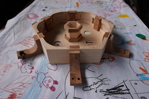
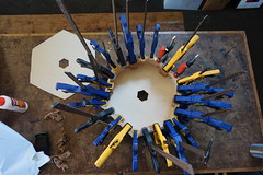
Hexachord interior assembled

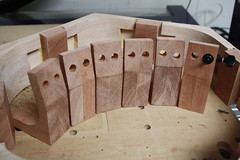
Hexachord top  New Hexachord Necks


I will also be running workshops at the FlipBooKit booth in the Maker Shed, so come on by. There will be a sneak peek of my new ‘How to Make a Custom Animation’ video playing in the shed along with the original assembly one. Here’s the finished animation from my demo!


See you there!

The Hexachord – Part 2

The Hexachord, Part 1

The Hexachord, Part 3


The Frame:


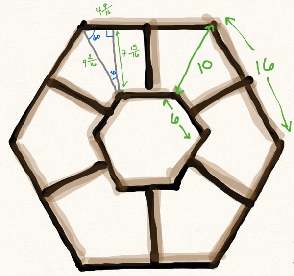
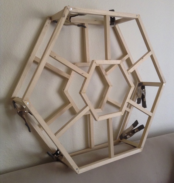
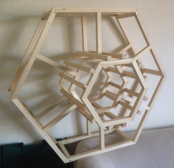
My Hexachord is built on a hexagonal frame, which I assembled with both glue and screws, cuz a heavy, three-foot-tall instrument is not something you want falling apart on you.  Two frames are held six inches apart to allow room for the mechanisms that control the sound chambers, and an additional structure extends to hold the sound chambers.


Frame schematics Partial frame Full hex frame


I have learned just how much precision wood joinery requires (for the record: invest in good measuring tools).  I have also discovered that CrashSpace members are all in love with the laser cutter (I know I will be too when I finally get around to using it), and everyone tells me how much easier it would be if I used it to make my mechanisms, or my sound chamber pieces, or… my lunch or something.  In some ways, I’m sure it would, but sometimes I just want to get in there and use my hands.  (Except for lunch.  I’m a lousy cook.)


The Mechanisms:


The hinges, like most everything else with the hexachord, are made of wood.  There are two different kinds, a basic butt hinge, and a ball/socket hinge.  I could have used pre-made metal butt hinges, but a) they would have stood out like a sore thumb amongst the lovely wood, and b) I am a glutton for punishment.  The kind of ball and socket hinges I wanted would have been a bit harder to acquire pre-made, so I set about making my own custom ones.


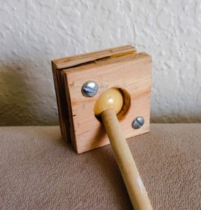
Ball socket joint


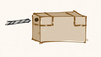
 I used a scroll saw and drill press (two tools very frequently used in this project) to build the socket in multiple layers.  The bottom and top layer have holes slightly smaller than the ball to give it an approximation of a complete socket.  In the end it doesn’t need more than a few points of contact, and having the socket in contact over the whole ball would have applied a lot more friction than I wanted.  The center is made of a square the same size as the top and bottom pieces, but with a hole a bit larger than the ball.  I ultimately cut it into four pieces and used only two as spacers on opposite corners.  The bottom piece was glued to the sound chamber, and the inside corner pieces were glued to that.  The top piece I connected with screws in case I needed to remove/replace the sound chamber from the rest of the instrument.  It’s a complicated thing; I like to leave myself the ability to repair.


There are nicely formed wooden spheres you can get, but finding just the right size wound up being more of a hassle than these wooden beads I tracked down at Michaels.  I used a dremel to widen one hole to the right size for the dowel, and voila!  A lovely, polished ball for the socket.  The whole construction works rather well.


(Note: when using a power tool to widen an existing hole, don’t hold it with a finger over the other opening.  Ow.)


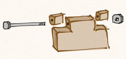
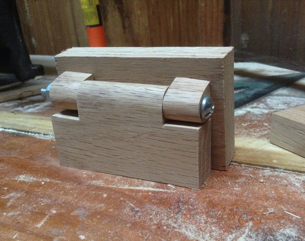
 The butt hinge was easier, as there are folks who have done very fine tutorials (this one is gorgeous).  If you drill the holes before cutting the side pieces, it’s much easier to get the pieces to line up properly.  I bolted the cut pieces together, and then glued the flat side of the small ones to another block.  Good, strong wood glue is important in something like this.  I like Titebond.  In future versions, I will probably use a glue more suited to musical instruments for the sound chambers, but it did the job pretty well here.


Wooden butt hinge sketch1


Wooden butt hinge sketch2


Wooden butt hinge


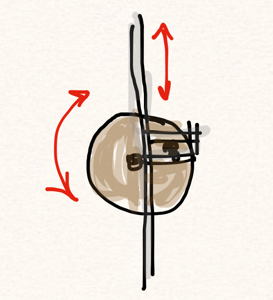
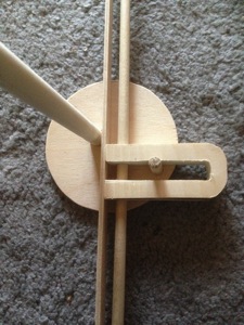
 Finally, there was the matter of making use of these hinges.  I wanted to be able to control the position of each sound chamber from the same side.  No dancing around to make it work (though that could be fun too).  As rotary motion is pretty easy to translate over long distances, I decided on using a knob for each sound chamber that connected to a scotch yoke mechanism.  It’s very efficient for converting rotary motion to linear.  There’s a disc and pegs, and ultimately several other smaller discs to hold stuff in place.  It can get wriggly if you don’t take charge.


Scotch yoke sketch

Scotch yoke wood


And those are the mechanisms.  I expect I’ll make full Instructables for the construction of each sooner or later.  Next time, the chaos of assembly, an interview, and videos!


The Hexachord – Part 1

As a Maker-in-Residence at the Intel Experience Store, I spent a whole lot of time playing around with motors, and you might recall that one of the projects I developed over the course of my time there was a motorized noisemaker.  In February, I started thinking more about rotary instruments, and about how there aren’t nearly enough of them.  Enter the Hexachord.


Building an instrument you’ve designed, particularly when you haven’t designed a full, complicated one before makes for a lot of modifications as you go.  As I love tinkering, that worked great for me.


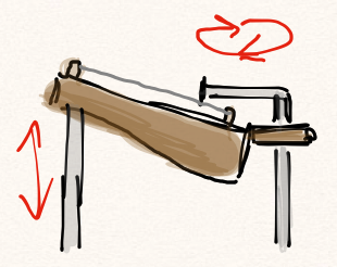
The Hexachord is a six-chambered string instrument with a spinning plectrum arm in the center that plucks each resonating chamber as it turns.  Each chamber is mounted on a hinge, so that it can be maneuvered in or out of the way of the plectrum arm.  This version’s spinning arm is powered by a motor from an old VCR.


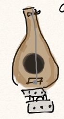
Chamber sketch side Chamber sketch top


As you might imagine, a new instrument this complicated is a difficult thing to get other people to understand while it’s still in the planning stages.  I had a rough idea in my mind from the beginning, of course, and I think it helped me develop it each time I tried to explain what it would look like and how it would work.


Getting it out of my head, (very) rough prototyping:


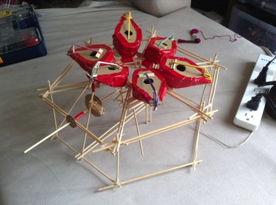
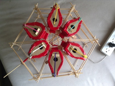
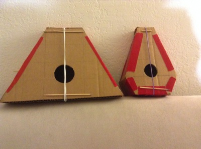
The first prototype was small, less than a foot across (to compare – the final version is over three feet tall), and made from cardboard, duct tape, rubber bands, and dollar store wooden skewers.  It’s not so much made to last; it has since fallen to pieces.  Cuz, y’know, duct tape.


Rough prototype rough prototype above


(The prototype in these pictures doesn’t include the plectrum arm, and is lying on its back, though it’s intended to be on its side with all the sound chambers facing forward.  So you can, like, hear it.)


The shape of the sound chambers was an early question.  I’d love to have been able to make them somewhat lute-shaped, as the prototype shows, which may pop up in a future version.  For this one, as I didn’t have access to a bending iron, I stuck to straight lines.  They both sounded decent, as far as wimpy cardboard resonating chambers using rubber bands as strings go.  The shape that resembled a balalaika won, for sound, for practicality, and for the aesthetic.  You’ll notice with my projects that the aesthetics are integral from the get go.  It’s just how my brain works.


prototype sound chambers

 Part 2, coming soon – building the frame and mechanisms!

Tech Disrupting

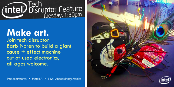
Cause & Effect Machine Flyer


Thanks to the wonderful folks at MakerEd, I got to be involved with the Intel Experience Popup Store this holiday season.  I was one of three “Tech Disruptors” at the Venice store (think Makers-in-Residence), who took apart old electronics and built new inventions from the parts.  We came up with some fun gadgets on our own and in collaboration with people who came into the store, especially kids.  There’s a special joy when children who have never seen the inside of a computer or car stereo crack into one for the first time, and it’s great to witness shy kids come out of their shells.  It’s so hammered into us that you Do Not mess with technology, you Do Not void the warranty, that breaking the taboo is wildly freeing.  Even the most rule-abiding is willing to join in when exclaim gleefully, “I want to see what’s inside, so I’m going to take this printer down to nothing.  Want to help?”  We’re curious by nature, it’s how we learn,  so why on earth should we keep kids from it?

One great thing from this experience was getting to know my fellow Tech Disruptors Carlyn Maw and Jen Fox.  The store’s run has ended, but we’re just getting started working together.  (Last Friday I introduced Jen to the fun that is shrink plastic, and she did little else the rest of the night.)

In any case, here are some of the things we came up with:

IMG_0213

 – Circuit Board Christmas Tree. Made from some of the many circuit boards we had on hand.  The dremel and I became very close during this process, we’re now BFFs.  It’s created from six half tree shapes, strung together with some old wires.  The colorful component ornaments were largely the work of guests and other employees at the Intel store, who all got very involved with our projects.  As a final touch, I charlieplexed some LEDs and plugged the whole thing into an Arduino.  A proximity sensor made the lights blink more quickly when you got up close.  I’m pretty proud of our result.


IMG_0338

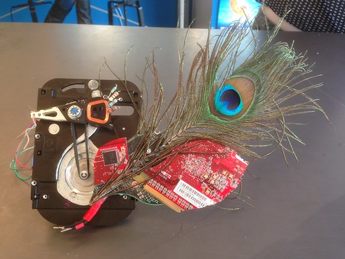
 – Hard Drive Bird.  It occurred to me that the actuator arm of a hard drive looks a bit like a bird’s head, so I carved up some wings/feathers from multiple colored circuit boards, and added a wire foot and peacock feather that I had lying around.  I swapped out the hard drive’s motor for a different stepper motor, and rigged up a belt made from gaff tape that transfers Arduino commands from the stepper to make the bird’s head twitch.  See the video!


the noisemaker, mounted

 – Gear Noisemaker.  This is something that evolved over the course of my time there (and is still evolving in a current project, which I’ll get into in another post).  It started out simple – a VCR motor and a cardboard gear, but quickly accumulated colorful electronic components for the gear’s face, and a plastic knife that would spin and hit whatever items we surrounded the gear with.  Among the noise items: parts from a 3.5″ floppy disk, a broken cd, random metal machine bits, copper wire strings, and old wind chimes.  By the end, I’d mounted the whole thing to a PVC frame, some guests added more strikers to the gear, and we incorporated it into the big Cause & Effect Machine.


cause & effect dog dish filler

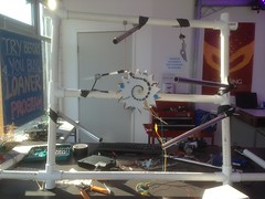
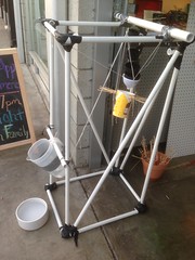
- Cause & Effect Machines.  Each of the Tech Disruptors was challenged to come up with and put on an event.  Rube Goldberg machines are so much fun, I thought it would be an interesting challenge to try to create one.  I built a seven-foot PVC pipe frame for us to build on and went nuts at dollar stores, and off we went.  The first day doing this project saw the creation of a dog waterer, and when we brought the activity out for our final showcase, Jen and I made a chain reaction that used a wooden skewer marble run, a lever triggered by jenga blocks, and two big metal enclosures attached to alligator cords that closed a circuit and started my noisemaker running.  Watch the videos!


Check out the full photo set on my flickr.  Carlyn made very detailed posts from her time at the store, and she has a lot on her flickr stream as well.